Instructions for use of GM328A transistor tester
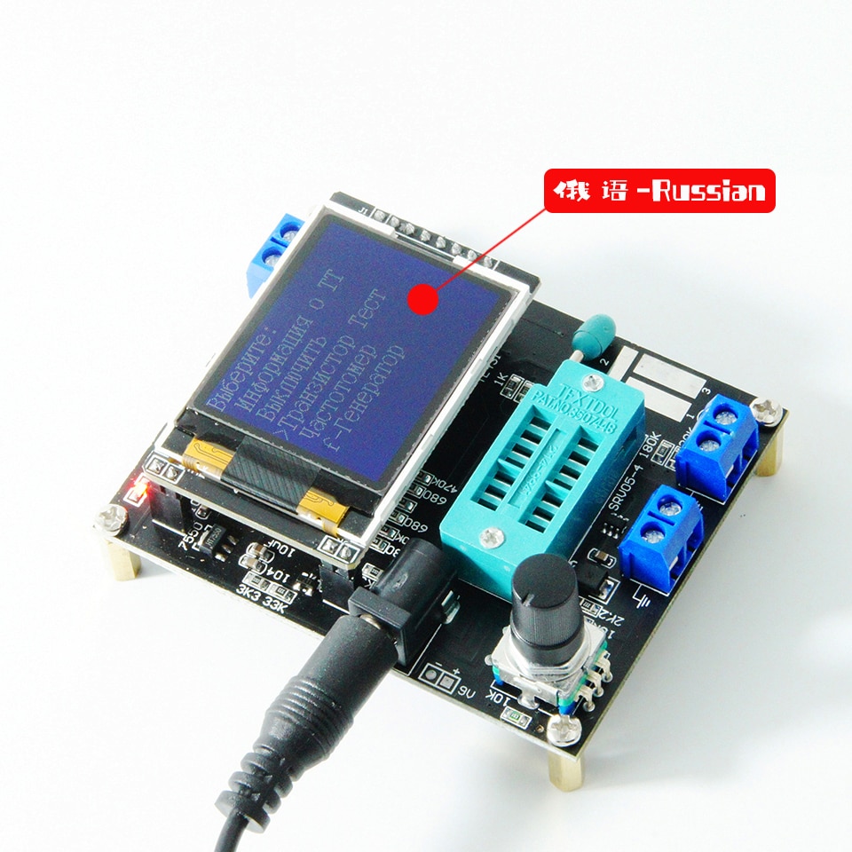
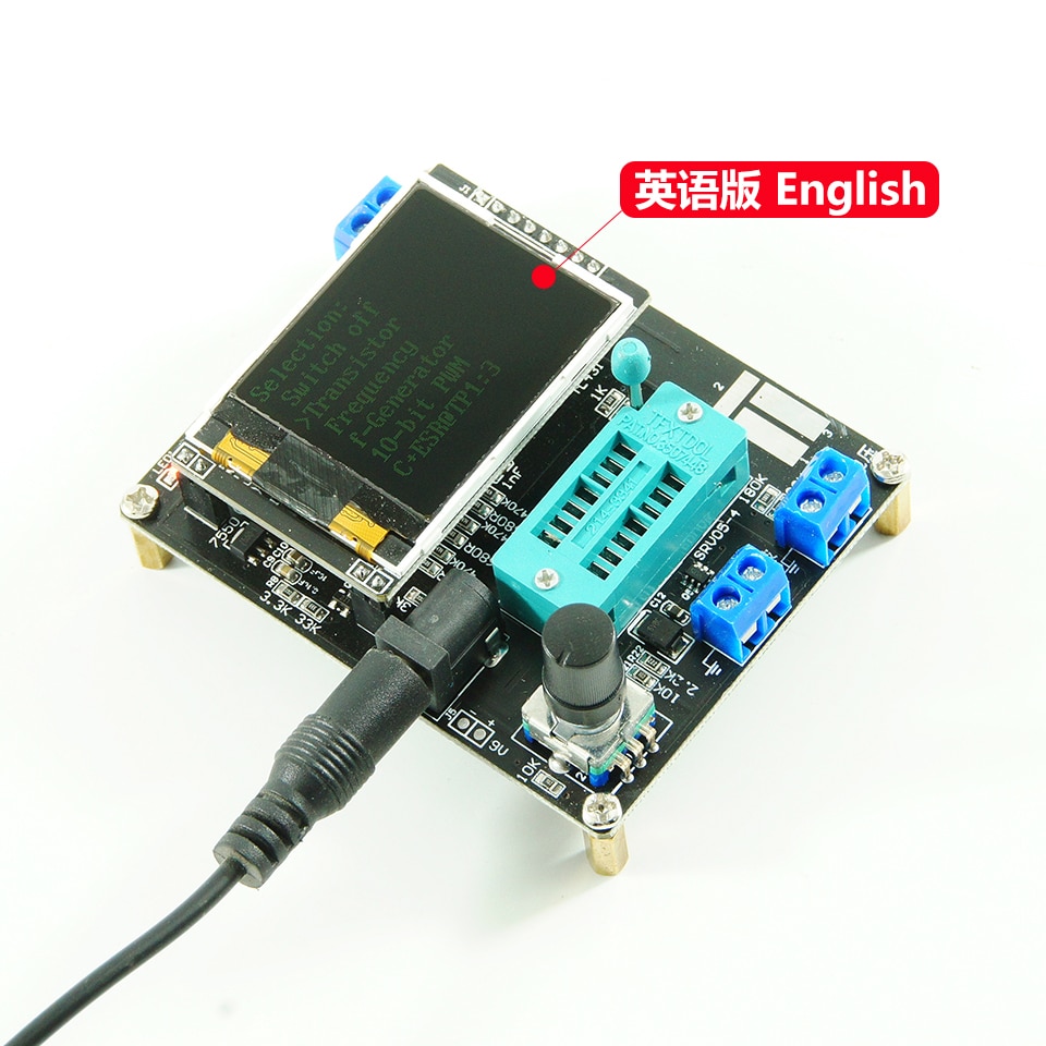
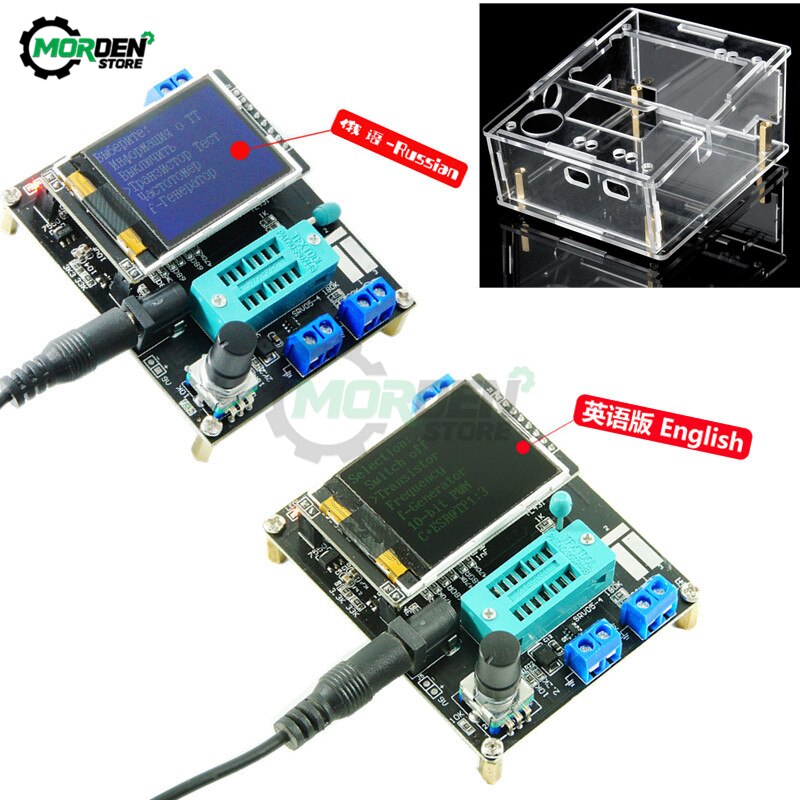
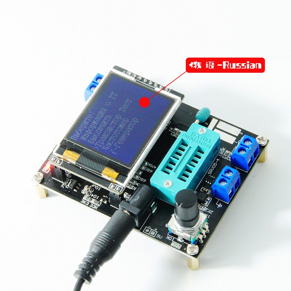
(The following functions are all available in English version, some functions are not updated in Russian version on July 23, 2020)
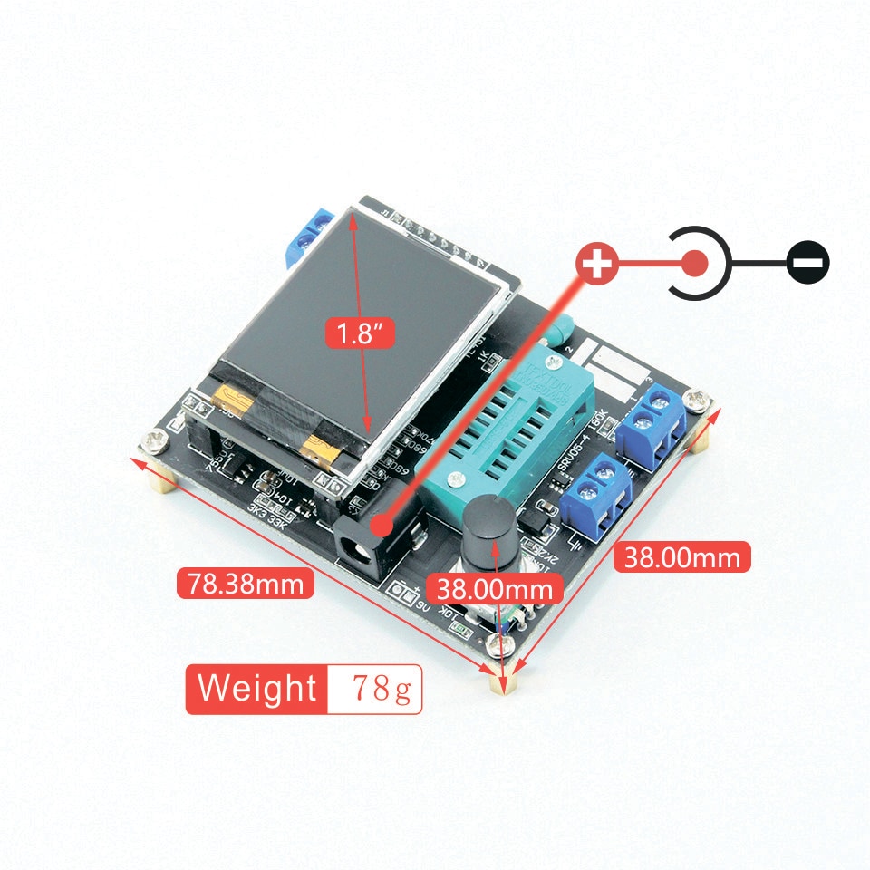
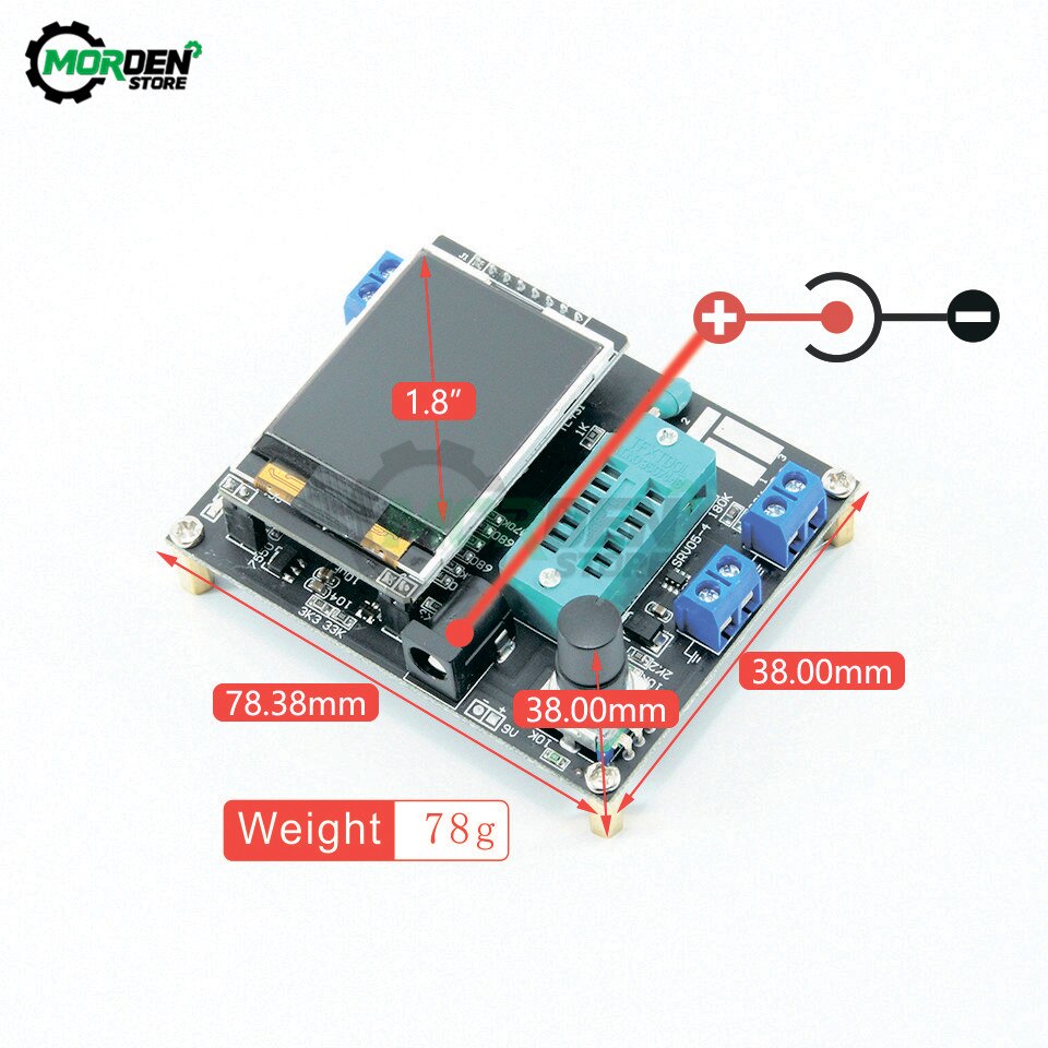
Input voltage: DC 6.8V-12V
Working voltage: about 30mA, measured when inputting 7.5V DC voltage
Transistor tester control
The tester is controlled by a rotary encoder switch,
The rotary encoder switch can have a total of 6 operations, short press, long press, left rotation, right rotation, hold left rotation, hold right rotation.
In the shutdown state, short press once to turn on the power and start the test.
After a test is completed, if the device is not detected. Long press the switch or the left and right rotary switch to enter the function menu. After entering the function menu, the left or right rotary switch can be selected up and down in the menu item. To enter a function item, short press the switch once. When you need to exit from a function, press and hold the switch.
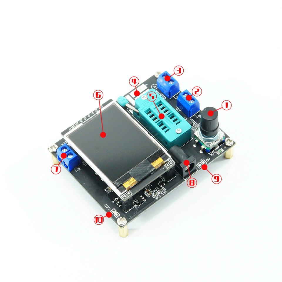
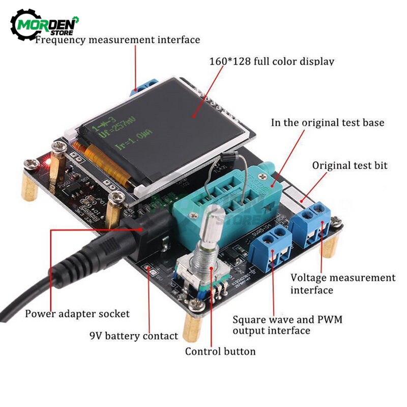
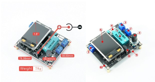
①Control button
②Square wave and PWM outputinterface
③voltage measurement interface
④Original test bit
⑤In the original test base
⑥160×128 full color display
⑦Frequency messurement interface
⑧Power adapter socket
⑨9V battery contact 9V
⑩Work indicator
Version function comparison
|
Features
|
English
|
Russian
|
|
Switch off
|
Yes
|
|
Transistor
|
Yes
|
|
f-Generator
|
Yes
|
|
10-bit PWM
|
Yes
|
|
 :3 :3
|
Yes
|
|
C+ESR@TP1:3
|
Yes
|
|
1-||-3
|
Yes
|
|
DS18B20
|
Yes
|
No
|
|
C(uF)-correction
|
Yes
|
|
IR_Decoder
|
Yes
|
No
|
|
IR_Encoder
|
Yes
|
No
|
|
DHT11
|
Yes
|
No
|
|
SelfTest
|
Yes
|
|
Voltage
|
Yes
|
|
FrontColor
|
Yes
|
No
|
|
BackColor
|
Yes
|
No
|
|
Show data
|
Yes
|
Test device
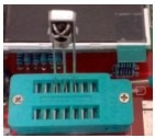
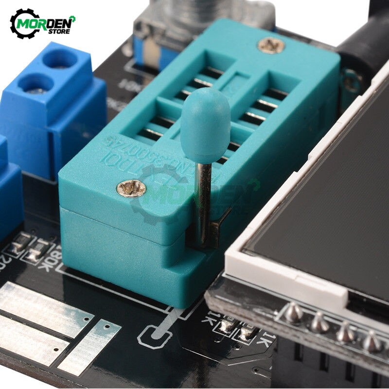
The tester has 3 test points, TP1, TP2, TP3. The distribution of these three test points in the test block is as follows:
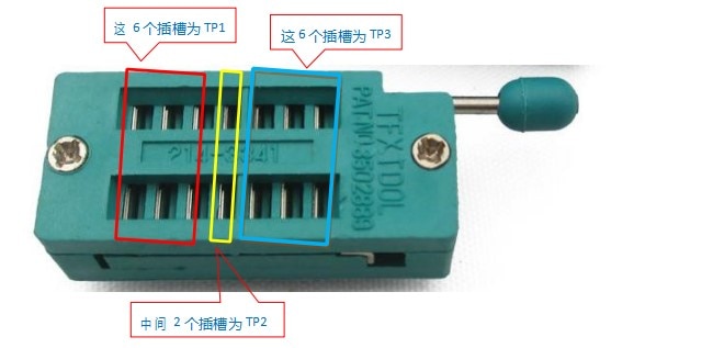
On the right side of the test seat is the test position of the patch component, there are numbers 1, 2, and 3 respectively, each representing TP1, TP2, and TP3
When testing a component with only 2 pins, the pins are not divided into the test order, 2 pins are arbitrarily selected for 2 test points, and the device pins with 3 pins are placed in three test points respectively, regardless of the order. After the test, the tester automatically recognizes the pin name and test point of the component, and displays it on the screen.
When testing a component with only 2 pins, if two test points TP1 and TP3 are used, it will automatically enter the continuous test mode after the test is completed, so that the components on TP1 and TP3 can be continuously and synchronously measured without pressing the switch. If you are using the “TP1 and TP2” or “TP2 and TP3” test, only test once. To test again, press the switch once.
Before testing the capacitor, discharge the capacitor first, and then insert the test socket for measurement, otherwise the single-chip microcomputer of the tester may be damaged.
1. Calibration
The tester calibration is used to eliminate the errors of its own components and make the final test results more accurate. Calibration is divided into quick calibration and full-function calibration.
The operation method of quick calibration: short-circuit the three test points TP1, TP2, and TP3 with wires, then press the test button while observing the screen. The color of the screen will change to black and white. After the prompt message “Selftest mode..?” appears, press the test button to enter the quick calibration process; if the prompt message “Selftest mode..?” appears, 2 seconds If there is no button in the clock, a normal test process is performed, and finally the resistance value of the three test points of TP1, TP2 and TP3 is displayed. After entering the quick calibration process, some data will appear on the screen, just ignore it. Wait until a flashing string appears on the screen
After “isolate Probes!”, remove the wires that short-circuit TP1, TP2, and TP3. After the character string “Test End” appears on the screen, the quick calibration is completed. When calibrating for the first time, use the full-function calibration method.
Full function calibration needs to be entered from the function menu, and a 220nf capacitor is also required. The full-function calibration performs a more comprehensive calibration process and will take longer. After entering the function menu, rotate the test button to the menu item “Selftest”, and then press the test button to enter the full-function calibration process. The flashing string “short Probes!” appears on the screen, which is the same as the quick calibration. Use wires to short-circuit the three test points and wait for the calibration process to proceed. When the flashing string “isolate Probes!” appears on the screen, remove the wires that short-circuit the three test points and continue to wait for the calibration process to proceed. When the character string “1-||-3> 100nf” is output, install the prepared 220nf capacitors on the test points TP1 and TP3. Wait until the screen prompts “Test End”, the full-function calibration process is complete.
2. Function menu
2.1 Switch off
2.2 Transistor
2.3 Frequency
Measuring frequency. Long press the test button to exit the frequency measurement function. The frequency measurement range is from 1Hz to above 1MHz. When the measured frequency is lower than 25KHz, the period is displayed
2.4 f-Generator
Square wave generator, there are multiple square wave frequencies to choose from, left or right rotation test button to switch different square wave frequencies, long press the test button to exit the square wave generator.
2.5 10-bit PWM
Pulse signal generator, rotate the test button left or right to adjust the duty cycle of the pulse, from 1%-99%. Long press the test button to exit the pulse signal generator.
2.6 C+ESR@TP1:3
Capacitance online measurement function, two wires can be drawn from TP1 and TP3, and the capacitance value and ESR of 2uF-50mF capacitors can be measured online. Note that the measured capacitance must be completely discharged before the test. If it is online measurement, the circuit where the capacitance is located must be completely disconnected It can only be carried out after electricity.
2.7
The continuous resistance measurement method continuously tests the resistance and inductance values installed on TP1 and TP3. The inductance of the measured resistance is less than 2100 ohms, and the inductance measurement range is 0.01mH-20H. Long press the test button to exit.
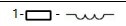
2.8 1-||-3
Capacitance continuous measurement method continuously tests the capacitance value installed on TP1 and TP3. For small-capacity capacitors, only this method can be used to measure the capacitance value. Measure the equivalent series resistance (ESR) of capacitors larger than 90nF, and the resolution of ESR is 0.01Ω. Capacitors above 5000pF show the rate of voltage drop after charging.
2.9 DS18B20 Russian version does not have this function
DS18B20 is a temperature sensor that uses single-bus communication to transmit data. It has the same package (TO-92) as a triode. The figure below shows the pin distribution of DS18B20.
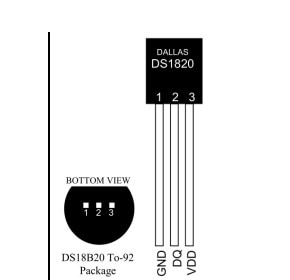
After entering the DS18B20 test function, the second line of the display shows the connection relationship between the test socket and DS18B20, “1=GND 2=DQ 3=VDD”, which means TP1 is connected to DS18B20 GND, TP2 is connected to DS18B20 DQ, and TP3 is connected to DS18B20 VDD . The tester cannot automatically recognize DS18B20, so you must follow the instructions on the second line to install
Install DS18B20. The tester can read the 12-digit temperature results measured by DS18B20, and display the corresponding temperature in Celsius on the third line with a resolution of 0.0625°C.
Scratchpad: The contents of the 8 storage units inside the DS18B20 read by the tester plus the CRC check value of the last byte. A total of 9 bytes.
Scratchpad BYTE
|
TEMPERATURE LSB
|
0
|
|
TEMPERATURE MSB
|
1
|
|
TH/USER BYTE 1
|
2
|
|
TL/USER BYTE 2
|
3
|
|
CONFIG
|
4
|
|
RESERVED
|
5
|
|
RESERVED
|
6
|
|
RESERVED
|
7
|
For example, the value read once is Scratchpad: EC014B467FFF0C102A has the following relationship:
Scratchpad Value BYTE
|
TEMPERATURE LSB
|
EC
|
0
|
|
TEMPERATURE MSB
|
01
|
1
|
|
TH/USER BYTE 1
|
4B
|
2
|
|
TL/USER BYTE 2
|
46
|
3
|
|
CONFIG
|
7F
|
4
|
|
RESERVED
|
FF
|
5
|
|
RESERVED
|
0C
|
6
|
|
RESERVED
|
10
|
7
|
64-bit ROM: The globally unique device ID of each DS18B20 read by the tester. The ID has a length of 64 bits. Divided into 3 parts.
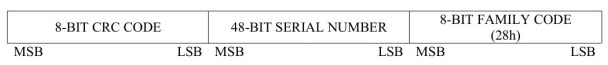
For example, the 64-bit ROM read by a DS18B20 is
64-bit ROM: 28FF4D58361604A1
Then there is
|
8-BIT FAMILY CODE
|
28
|
|
48-BIT SERIAL NUMBER
|
041636584DFF
|
|
8-BIT CRC CODE
|
A1
|
Note: Except that the temperature value (TEMP) is in decimal, the rest are in hexadecimal.
The temperature measurement range of DS18B20 is -55℃-125℃. Long press the test button to exit this function.
2.10 C(uF)-correction
This function is used to correct the measured value of large-capacity capacitors. The default value is 0%. That is, there is no correction, the setting range is -0.2%-8%, when it is a positive value, it will reduce the measured value of the capacitance, and when it is a negative value, it will increase the measured value of the capacitance.
After setting, long press the test button to exit.
2.11 IR_Decoder Russian version does not have this function
Infrared remote control decoding function. This function requires a 1838 integrated infrared receiver (pulse type). After entering this function, observe the prompt on the display screen. The second line will display the character string “”1=DOUT 2=GND 3= VCC”, the character string means the connection relationship between the 3 test points on the tester and the infrared receiver, and the connection must be strictly in accordance with the instructions. Only one infrared receiver can be installed on the test seat empty or correctly. For other components, it is not allowed to short-circuit the test points with wires to avoid unpredictable failures. The following figure shows the installation direction of an example infrared receiver.
TP1 is connected to the DOUT pin of the infrared receiver, TP2 is connected to GND, and TP3 is connected to VCC.
The infrared remote control decoding function supports two infrared remote control encoding formats.
Format one
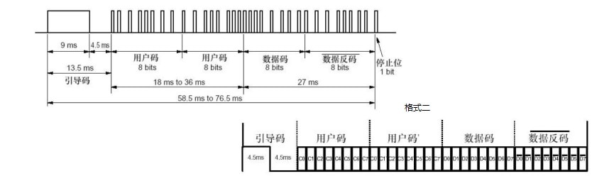
The above two formats are roughly the same, the difference lies in the length of the pilot code. Format one is 9MS and format two is 4.5MS.
Infrared remote control decoding function uses uPD6121 to indicate format one, and TC9012 to indicate format two.
Instructions
The infrared remote control decoding function can only be accessed from the function menu. Before entering the infrared remote control decoding function, there must be no components on the test base and the square wave output terminal. Enter the infrared remote control decoding function, after the “standing by…” string appears on the display, install the integrated infrared receiver into the test socket and lock it. Then you can aim the remote control at the infrared receiver to launch. If you can identify the code used by the remote control. The third line will display a string of “>>>>>>>>>>>” characters, which means a successful decoding, and the fourth line will display the encoding format used by the remote control. The fifth line shows the first byte of the user code (user code1), and the sixth line shows the second byte of the user code (user code2). The seventh line shows the data code (data) and data inverse code
(~data), the last line is integrated display 32bit. All values of infrared decoding function are expressed in hexadecimal format.
The infrared decoding function only supports single-key mode, not continuous mode. When testing this function, it is found that several TV remote controls used for testing are all TC9012, the small Mp3 remote control is uPD6121, and the remote control of the air conditioner cannot be recognized :-(). Due to conditions, no more tests can be done.
To exit from this function, first remove the receiving head on the test seat, and then press and hold the rotary encoder switch to exit.
2.11 IR_Encoder Russian version does not have this function
Infrared remote control coding function, this function requires an infrared light emitting diode. The tester can control the infrared light-emitting diode to realize the function of an infrared remote control. Since the tester can only provide a driving current of about 6mA at most, the control distance cannot be compared with a normal infrared remote control. In the case of aiming at the infrared receiver, it is about within 2 meters.
The infrared remote control code supports two formats, which are the same as the decoding format of the infrared remote control described above. Also use uPD6121 for format one and TC9012 for format two.
Instructions
The infrared remote control coding function can only be accessed from the function menu. Before entering the infrared remote control coding function, there can be no components on the test base and the square wave output terminal. After entering the infrared remote control coding function, connect an infrared light-emitting diode to the square wave output terminal. The negative electrode of the infrared light-emitting diode is connected to the ground and the positive electrode is connected to the output. Wires can be used to extend the positive and negative electrodes of the infrared light-emitting diode to facilitate operation. The long leg of the infrared LED is positive and the short leg is negative.
The leftmost column of the display is a “>” symbol, indicating the parameter currently being set. Short press the test button to switch between each setting item “>”. The second line “protocol” sets the encoding format to be used. Rotate the test button left and right to switch between “uPD6121” and “TC9012”.
The third and fourth lines “user code1” and “user code2” set the first and second bytes of the user code, the left-handed test button can be reduced by 1 unit, and the right-handed test button can be increased by 1 unit.
The fifth line sets the data code (data), the left-handed test button can be decreased by 1 unit, and the right-handed test button can be increased by 1 unit. The inverse code of the data is automatically calculated by the data code and cannot be set manually.
When setting the value of the user code and data code, in addition to rotating the test button left and right to change its value in units of 1, it can also be increased in units of 0x10. The operation method is to press and hold the test button, but the long time cannot be too long. If it is too long, it will exit from this function. This degree is not easy to be sure at first. The sixth line is the emission control “emit:”. When the “>” sign is moved to this line, rotate the test button left and right to emit infrared rays according to the data set above. When you turn the test switch, you can see a “->” symbol flashing quickly. Indicates that data was transmitted once.
Operation example:
To use the infrared coding function to control an electrical appliance, you must first know the coding format of the remote control that controls the electrical appliance. So the first step is to use the infrared decoding function to read the code value of a button on the remote control.
For example, if the TV is a Samsung LCD TV, press the volume down button of the remote control, the decoded value is
TC9012 user code1=07 user code2=07
data=0B ~data=F4
All 32bit=F40B0707
Record the above data, and then in the infrared coding function, respectively set the protocol: TC9012 user code1=07 user code2=07
data=0B ~data=F4
Then move the “>” symbol to emit:
>emit:
The infrared light-emitting diode connected to the square wave output terminal of the transistor tester is aligned with the position of the infrared receiver of the TV, and the test button is turned to start a transmission, and the TV can be controlled to reduce the volume.
To exit from this function, first remove the infrared LED connected to the tester, and then long press the test button to exit
Note: The transistor tester only supports two encoding formats, TC9012 and uPD6121. The values are all expressed in hexadecimal
2.12 DHT11 Russian version does not have this function
DHT11 is a temperature and humidity sensor, in addition to measuring temperature, it can also measure humidity. The pin distribution is shown in the figure below.
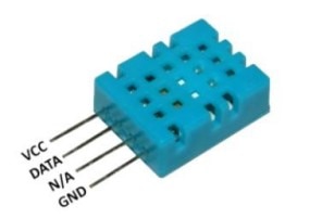
After entering the DHT11 test function, the second line of the display shows the connection relationship between the test socket and DHT11, “1=GND 2=DQ 3=VDD”, indicating that TP1 is connected to DHT11’s GND, TP2 is connected to DHT11’s DATA, TP3 is connected to DHT11’s VCC . The N/A pin can be connected to TP1 together with the GND pin, or it can be left floating. After the test is successful, “TEMP” represents the temperature value, and “HUMI” represents the humidity value. All are displayed in decimal.
To exit the function, long press the test button
2.13 SelfTest
Full-function calibration function.
2.14 Voltage
DC voltage measurement, up to 50V can be measured. The voltage to be measured should be input from the “voltage measurement” interface (do not input the measured voltage from other interfaces such as the “frequency output” interface, which will damage the microcontroller). To exit this function, quickly rotate the encoder left and right.
2.16 FrontColor Russian version does not have this function
Set the foreground color, that is, the color of the character. Rotate the test button to the left or right to change the corresponding color component value. Short press the test button to select the three primary colors of red, green and blue to be changed. The 16-bit color code uses RGB (565) The format corresponds to the maximum value of 31 for red, 63 for green, and 31 for blue. After setting, long press the test button to save and exit. Be careful not to set the foreground and background colors to the same color, otherwise nothing will be visible. If this happens, shut down and perform a quick calibration. The method to enter the quick calibration is described above, and the screen color will become black and white. Modify the screen color immediately after the quick calibration is completed.
2.17 BackColor Russian version does not have this function
The method is the same as setting the foreground color, but this is to modify the background color.
2.18 Show data
Display the internal data of the tester, from which you can observe the test function of the tester.


Reviews
There are no reviews yet.