

Description
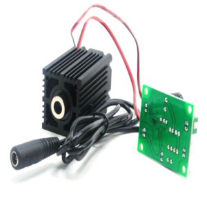
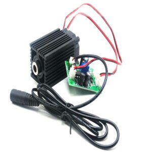
- Motor Type: Stepper Motor
- Certification: CE
- Origin: CN(Origin)
- Model Number: 5-axis interface cable socket HX2.54
- feature: anti-reverse function
- feature1: Peripheral wide voltage input
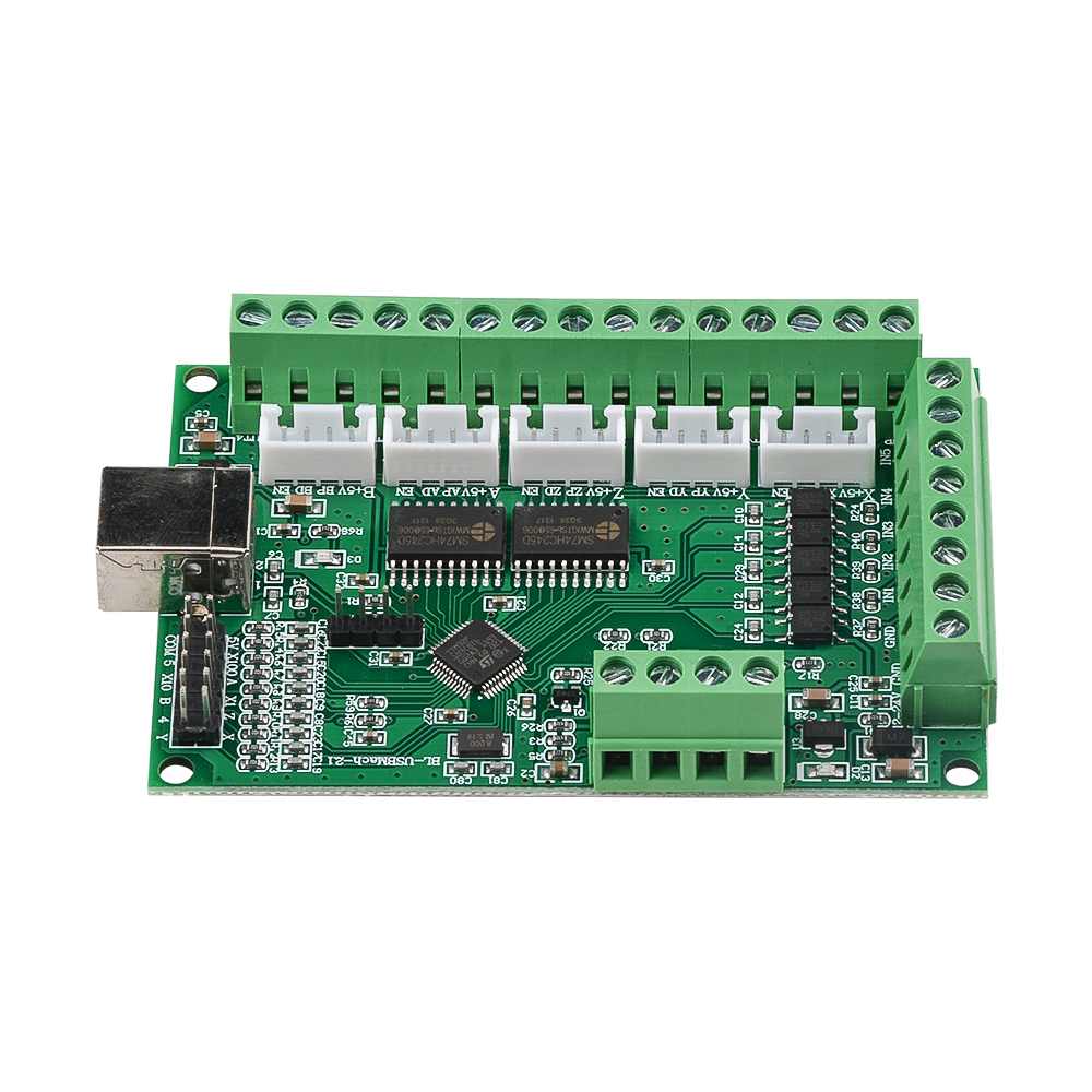
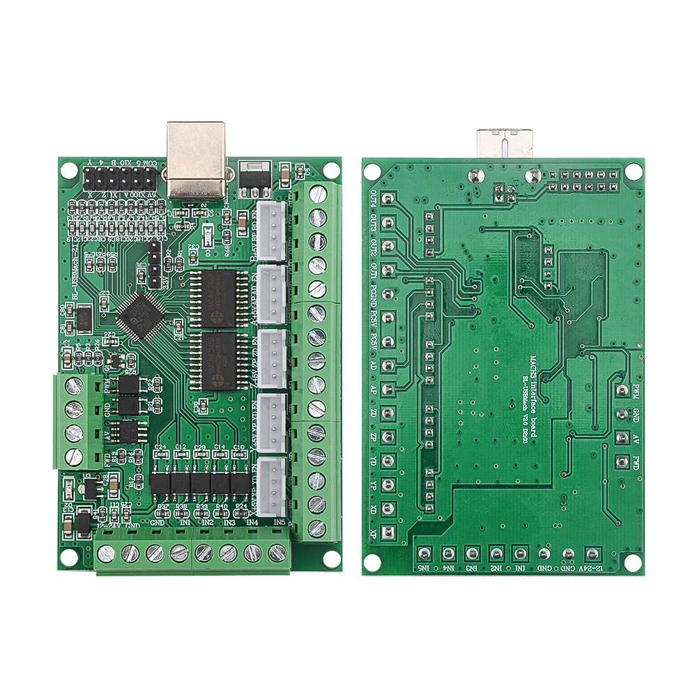
- feature3: MACH3 V2.1 five-axis engraving machine motherboard
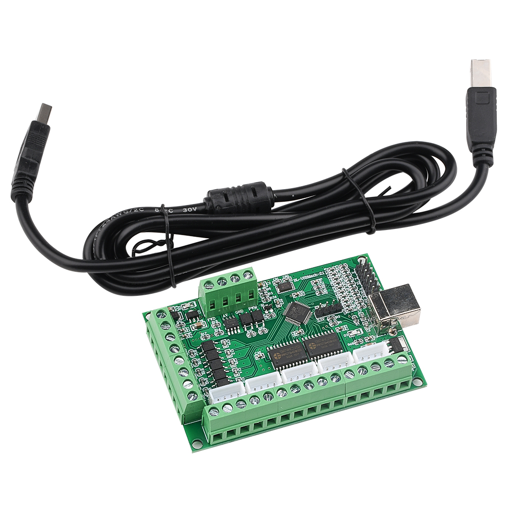
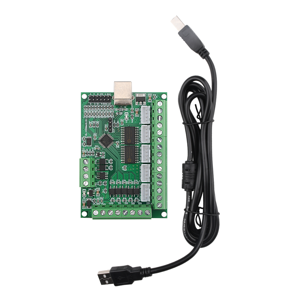
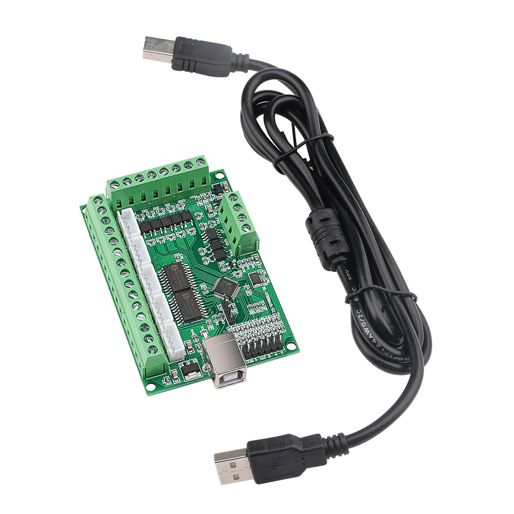
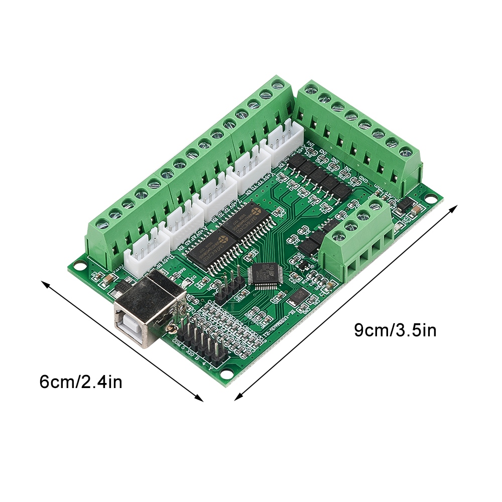
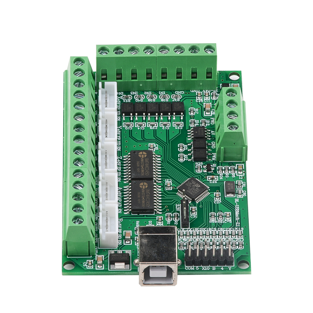
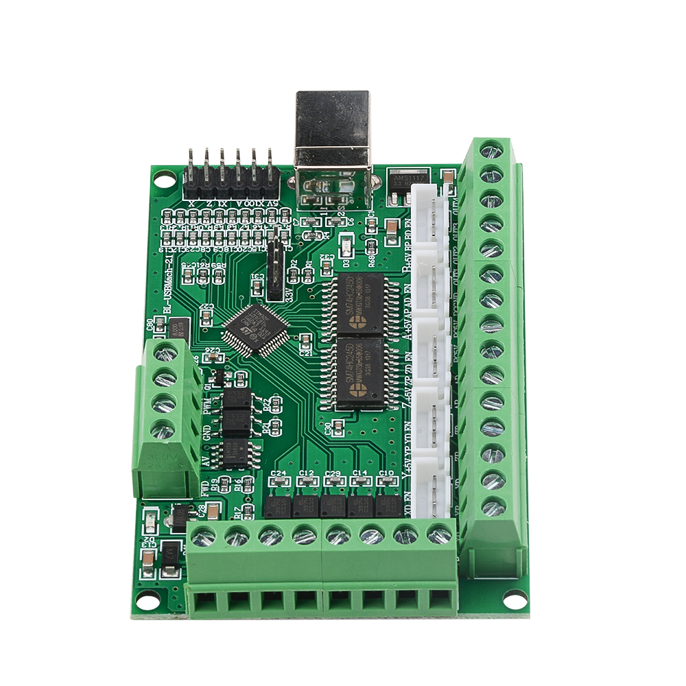
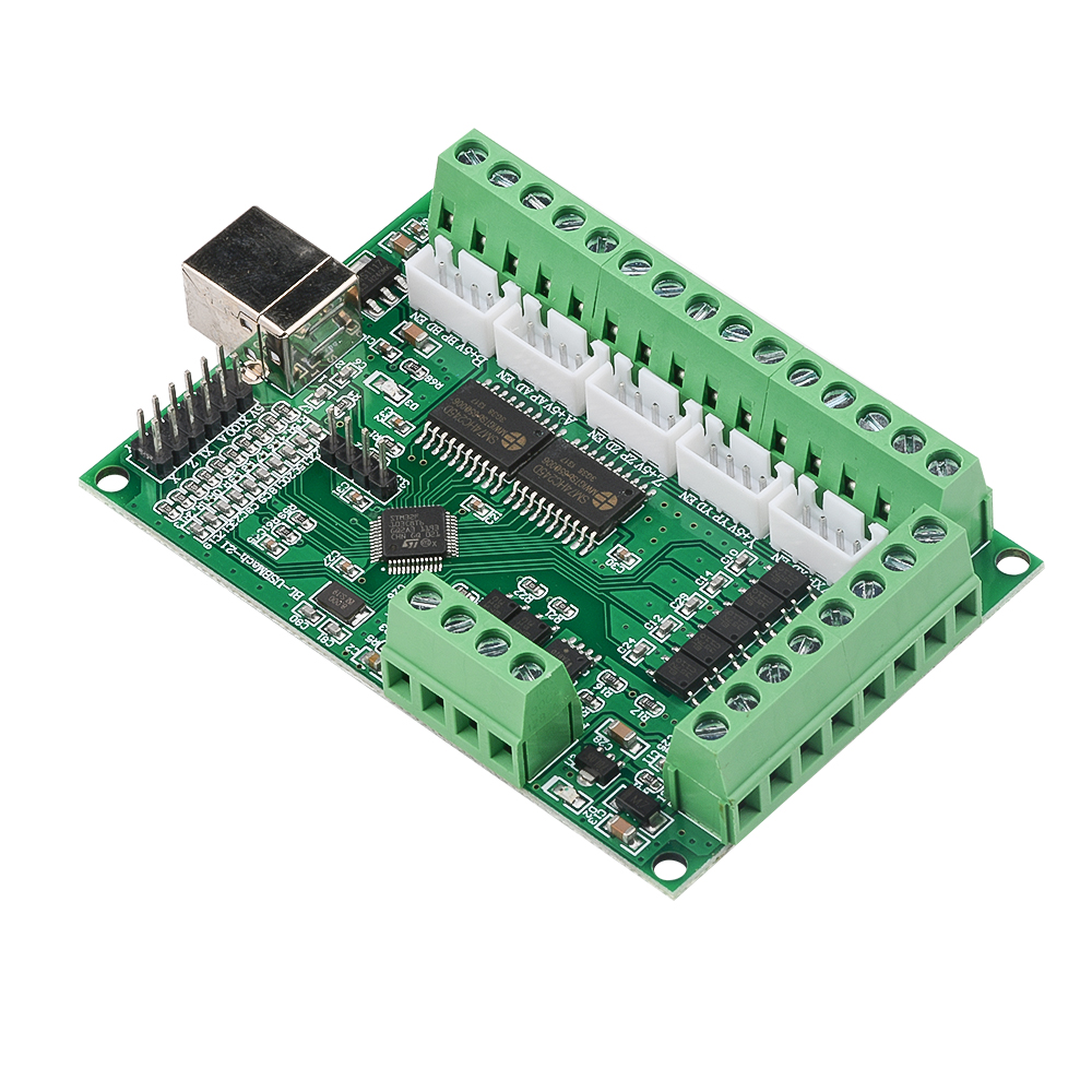
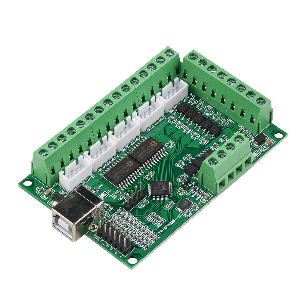
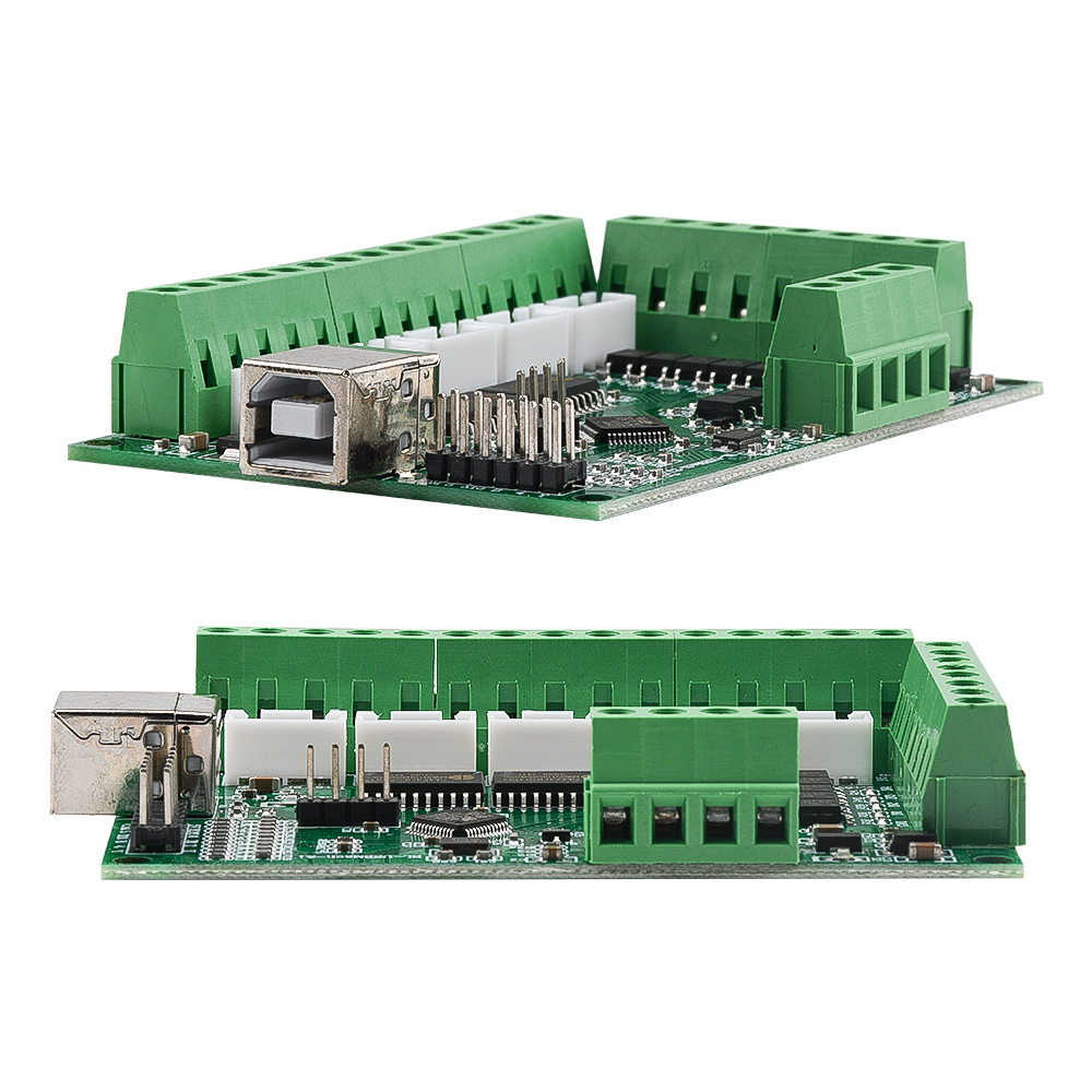
MACH3 V2.1 five-axis engraving machine motherboard CNC motion control card 5-axis stepper motor drive interface board
Product introduction:
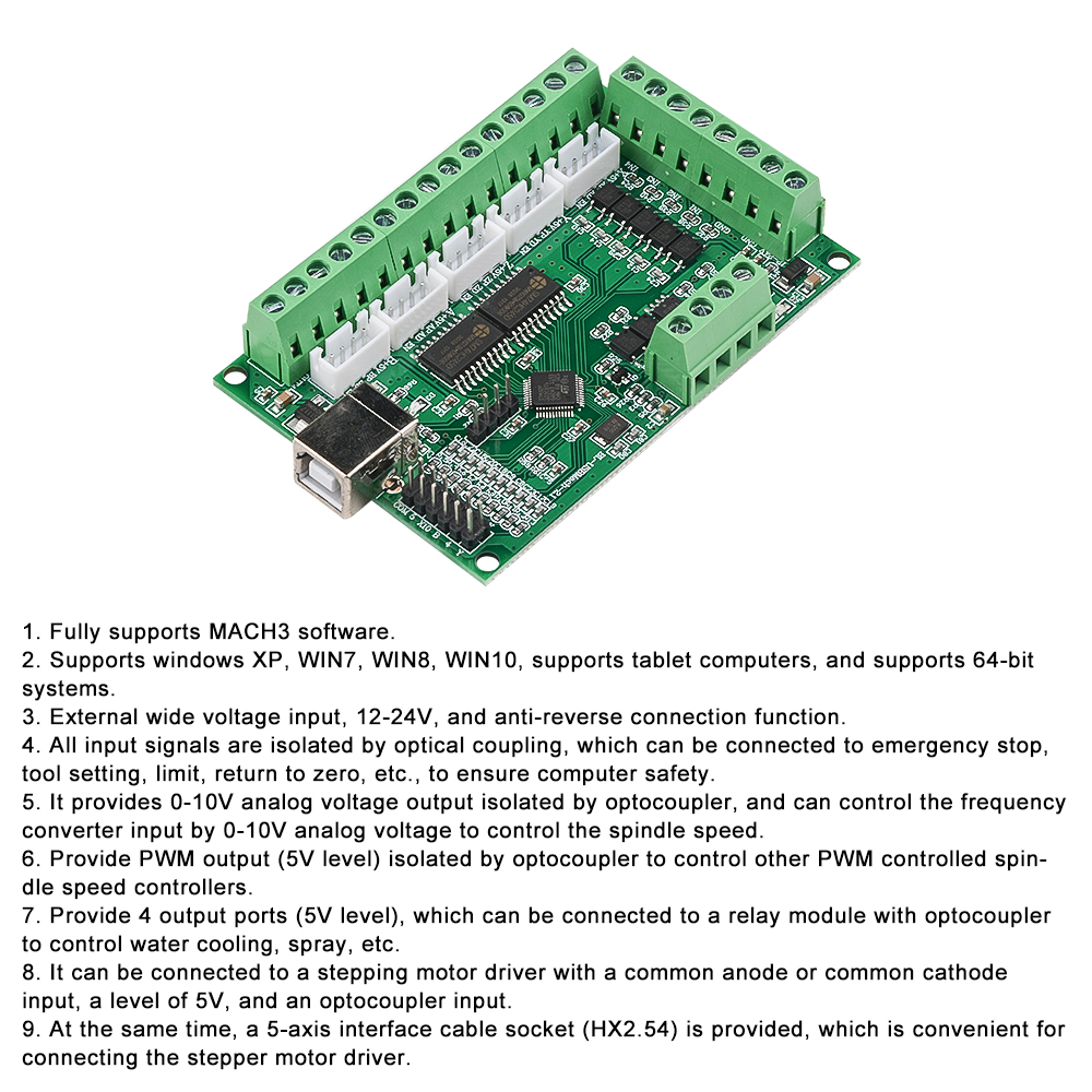
1. Fully supports MACH3 software.
2. Supports windows XP, WIN7, WIN8, WIN10, supports tablet computers, and supports 64-bit systems.
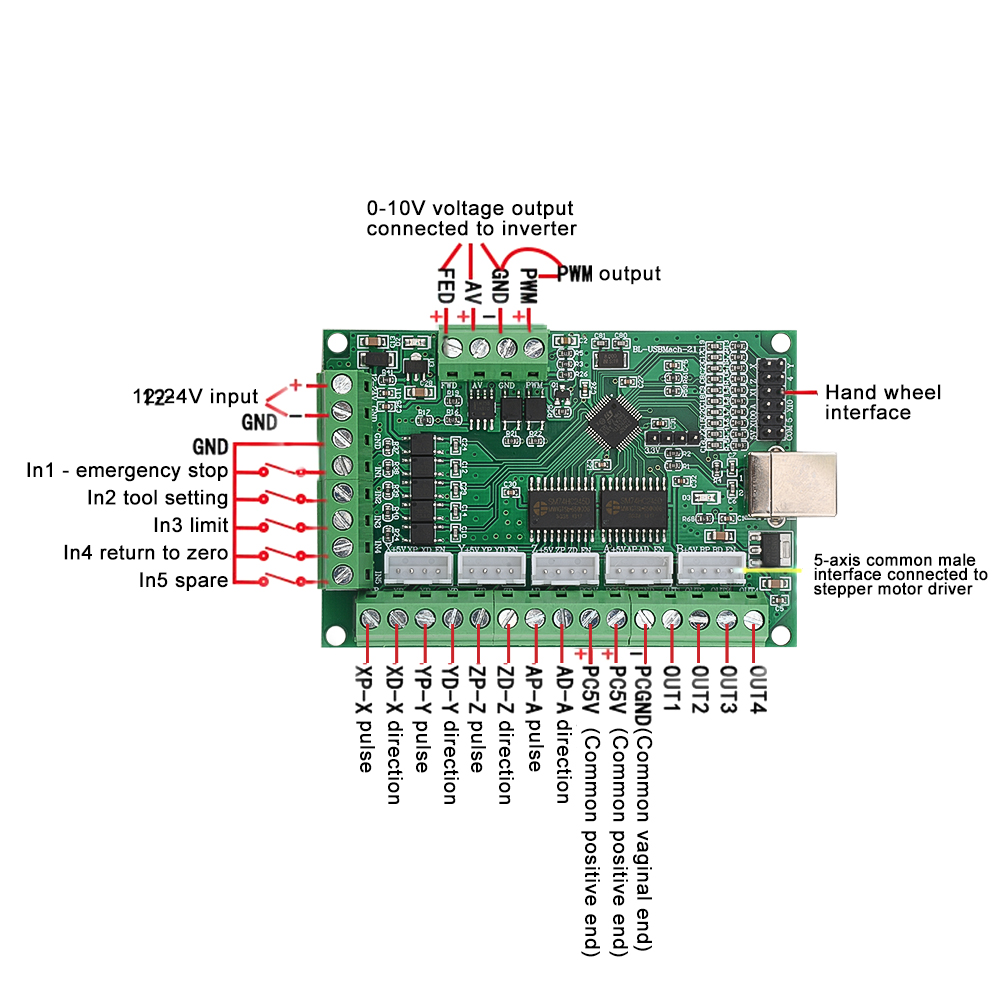
3. External wide voltage input, 12-24V, and anti-reverse connection function.
4. All input signals are isolated by optical coupling, which can be connected to emergency stop, tool setting, limit, return to zero, etc., to ensure computer safety.
5. It provides 0-10V analog voltage output isolated by optocoupler, and can control the frequency converter input by 0-10V analog voltage to control the spindle speed. , The
6. Provide PWM output (5V level) isolated by optocoupler to control other PWM controlled spindle speed controllers. To
7. Provide 4 output ports (5V level), which can be connected to a relay module with optocoupler to control water cooling, spray, etc.
8. It can be connected to a stepping motor driver with a common anode or common cathode input, a level of 5V, and an optocoupler input.
9. At the same time, a 5-axis interface cable socket (HX2.54) is provided, which is convenient for connecting the stepper motor driver.
The inverter generally needs to be set:
1. Set the inverter to external terminal start.
2. Set the frequency control mode of the inverter to analog (0-10V) input control.
Quickly test whether the inverter has been set up:
1. The inverter does not need to be connected to the interface board first.
2. Short-circuit the FWD and COM of the inverter, and short-circuit the 10V and VI of the inverter. Connect the spindle. (Of course, it is better to connect the potentiometer to the 10V, VI and GND of the inverter according to the figure).
3. Power on, if the inverter can run at the maximum speed and the spindle rotates normally, it basically means that the setting is correct. (If a potentiometer is used, the speed is adjustable).
4. In this way, you can connect to the interface board according to the above method
Note: Generally, the inverter has multiple control methods, so it is generally necessary to set it to run. It is basically impossible to wire without setting, so it is a necessary step to check the instruction manual of the inverter and set it up!
Package Included:
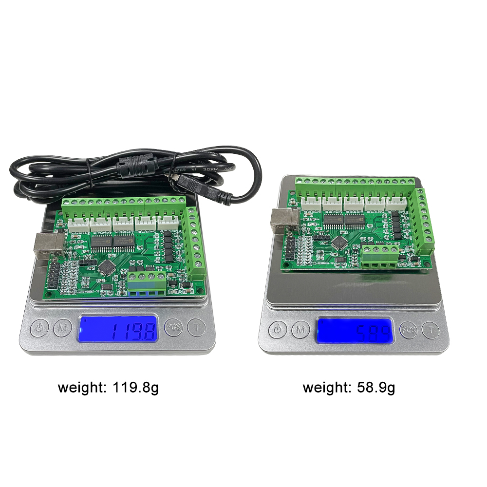
Engraving machine motherboard X1
USB data cable X1